This siren will have to be mounted on the pole where the model two does so there can be more room in the garage so we will need help with ideas on how to get it on the pole. I will also post more information about this siren.
Also one thing I should point out is that it is 120 volts per motor! The only reason it is 240 is too power the chopper AND the rotator.
If you where to only want to run one (either the rotator or the chopper I have only the chopper running here) you would just hook up 120 to the neutral and the hot to the chopper.
I will post more pics and more information about this siren later. I will also post a lot of pics just have to get everything off my camera. I am doing the attack manually with a stop watch to get it perfect.
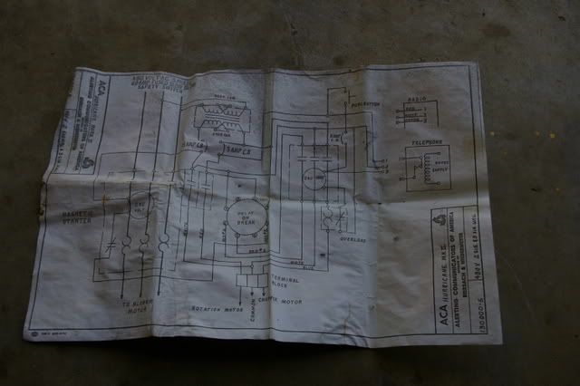
Hopefully Adam and me can figure out that crazy control panel. Also I found the control panels wiring diagram in the pocket of the cabinet (which will be posted later)
And as promised here are the pictures.
Wiring Diagram for the control panel.
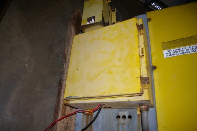
Control panel with door closed
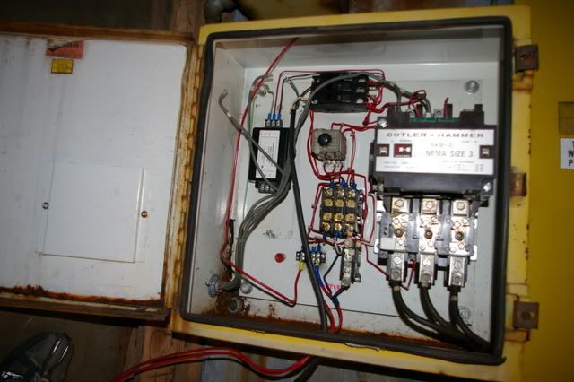
Control panel with door open
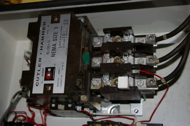
480 Blower thing
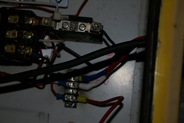
Chopper wiring
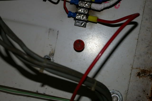
Some red button in the cabinet
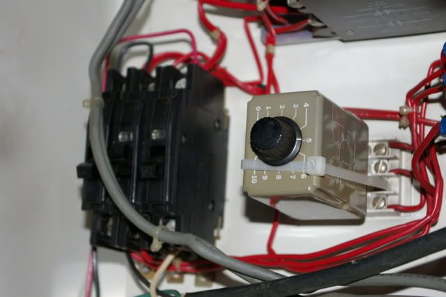
Time delay adjustment knob
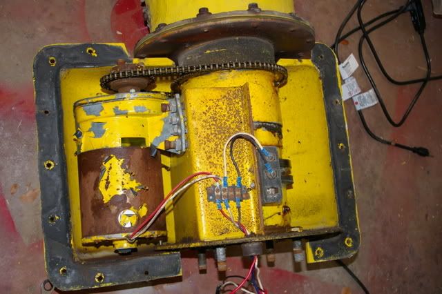
Inside of rotator with terminal strip for wiring. This shows that the rotator is 120V and the chopper motor is 120V
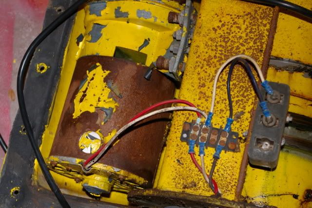
Closer of the rotator motor and the terminal strip
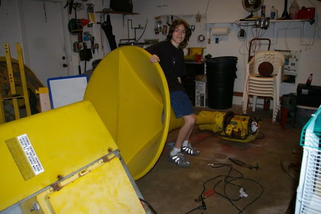
Me by the horn